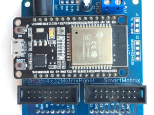
Description
This shield is for easily controlling P10 LED Matrix panels using with a board STMSTM32F103C8T6 (aka the Blue Pill).

Assembly Required: This shield is a kit, but uses all through hole parts so is easily assembled.
It is designed to work with the DMD_STM32 with Unicode fonts support library.
NOTE: Please check out the libraries’ Github page for more information.
The controller contacts that are not used for LED panels control are brought to the board. The microcontroller Serial ports (1-3) are separately brought out, through which data can be transmitted to the controller.
The DMD-STM32 Shield has a free area with contacts, on which additional elements or sensors can be mounted.
You can use one of two interfaces (SPI1 or SPI2) to control the LED panels.
The DMD-STM32 Shield provides places for installing a 3.3V-5.5V 74LCX245WMX bidirectional level converter chip to control the LED matrix.
Note: P10 LED panels work fine with 3.3V logic levels, but do not use a long ribbon cable to connect the DMD-STM32 Shield to the panel (<15 cm).
The microcontroller is powered from 3.3 V, therefore the board is equipped with an AMS1117 voltage converter (5V to 3.3V).
Controlling LED panels requires a lot of microcontroller resources, so the computational resources of Arduino or ESP are not enough to control large LED screens. The use of an STM32 microcontroller allows you to control very large LED screens (up to 80 panels). The panels are only about $8 from aliexpress.
“DMD_STM32 with Unicode fonts support” library also allows you to use various national fonts (Cyrillic, Arabic, etc.) and even create them yourself using “Excel fonts editor-converter for Adafruit, UTFT, Squix, ILI9341_t3, OLED_I2C“!
This board makes wiring them really simple! The board just slots directly onto the input header pin, uses the ribbon cable that comes provided with most of these panels to connect the pins of the output header and has screw terminals to connect the power cable that comes with most panels.
The use of an STM32 microcontroller allows you to control very large LED screens. The information displayed on the screen can be obtained from additional sensors or via the Serial port of the STM32 board.
This really makes using the display as simple as possible. Making use of the cables that comes with the display allows the board to be smaller and less expensive.
There are free zone with contacts on board for mounting various sensors or drivers.
DMD-STM32 Shield for P10 LED Matrix Panel Features:
- Compatible with DMD_STM32 with Unicode fonts support library
- On board four 16 pin male header (2×8) (two with 3.3V logic level for using SPI1 or SPI2 and two with 5V logic level)
- Operates at 5V
- On board voltage converter 5V to 3.3V
- On the board zone for a level converter microcircuit 74LCX245WMX
- On board free zone with contacts for mounting various sensors or drivers
- Dimensions are 120mm x 60mm
What will you get in the package?
Each DMD-STM32 Shield is a kit and comes with the following:
- DMD-STM32 Shield PCB
- 10uF 25V Capacitor
- 100uF 25V Capacitor
- One 16 pin male header (2×8)
- Voltage converter 5V to 3.3V AMS1117 (option)
- 2Pin Plug-in Screw Terminal Block Connector 5.08mm
What is NOT included?
The following components are not provided, but may are required to use this board.
- Compatible HUB12 P10 LED Matrix Panel http://alii.pub/5ypnqz . Most panels come with a power cable, this board requires this.
- STMSTM32F103C8T6 (aka the Blue Pill) http://alii.pub/5z021l
- Three 16 pin male header (2×8)
- Level converter microcircuit 74LCX245WMX
- Power supply 5V – $8 from Aliexpress http://got.by/4ekh09
Board assembly
To assemble the boards, place the parts on the PCB as indicated by the markings on the PCB. All parts are places on the top of the PCB (as seen in the photos above).
STMSTM32F103C8T6 is placed on the board in accordance with the marking (USB).
NOTE: Please pay attention to the polarity of the capacitor and the direction you are soldering the connectors!
Connecting the shield to the LED matrix
Insert the ribbon cable that came with the display into the connector on the shield, insert the other end into the connector of the LED matrix panel.
Plug the power wire that came with the display into the power pins of the panel. Attach the power wires to the 2Pin screw terminals on the shield (Pay close attention to the polarity!)
Powering the DMD-STM32 Shield
DMD-STM32 Shield require a 5V power supply capable of doing roughly 500mA of current.
Use a separate 5V 20 – 40A adapter directly to the panel (depends on the number of LED panels).
Using the DMD-STM32 Shield
To use the display you will need to install the DMD_STM32 with Unicode fonts support library.
It can be installed from the Arduino library manager or download directly.
If you want use SPI 1:
#define DMD_PIN_A PB11
#define DMD_PIN_B PB12
#define DMD_PIN_nOE PB1
#define DMD_PIN_SCLK PB10
SPIClass dmd_spi(1); // We’ll use SPI 1
DMD dmd(DMD_PIN_A, DMD_PIN_B, DMD_PIN_nOE, DMD_PIN_SCLK, DISPLAYS_ACROSS, DISPLAYS_DOWN, dmd_spi);
If you want use SPI 2:
#define DMD2_PIN_A PB8
#define DMD2_PIN_B PB9
#define DMD2_PIN_nOE PB0
#define DMD2_PIN_SCLK PA8
SPIClass dmd_spi2(2);
DMD dmd2(DMD2_PIN_A, DMD2_PIN_B, DMD2_PIN_nOE, DMD2_PIN_SCLK, DISPLAYS_ACROSS, DISPLAYS_DOWN, dmd_spi2);
| KIT 1 | KIT 2 |
| PCB with soldered converter 5V to 3.3V AMS1117 and all elements and connectors for connecting the LED Matrix panel (capacitors, connectors) | PCB with soldered all elements and connectors for connecting the LED Matrix panel (capacitors, connectors) without converter 5V to 3.3V AMS1117 |
More information
If you are looking for installation instructions or more information about the board, please checkout Github page.
Coding Support
Please note that we can not provide coding support for this item. We can offer some troubleshooting advice on getting them working and we can point you to some examples we have created using these board, but I will not be able to give support on building something specific.


