Opis
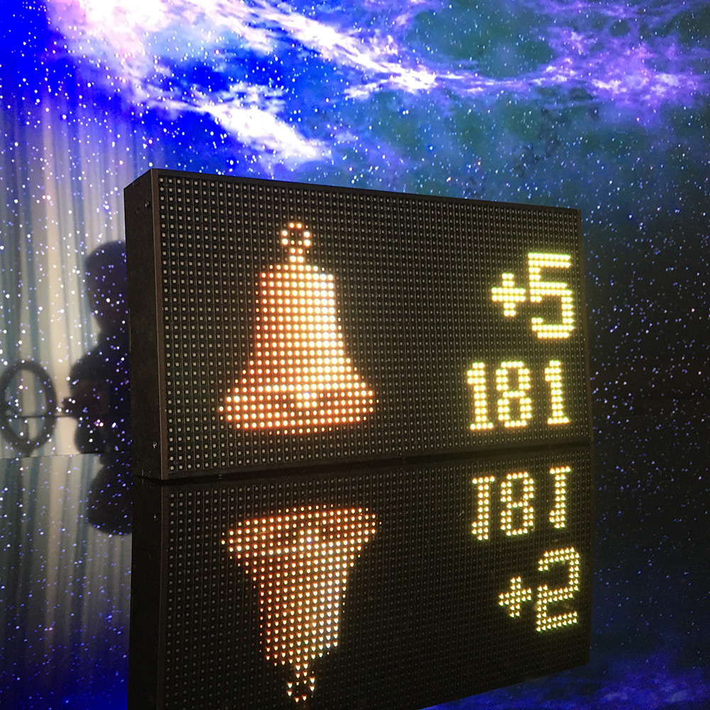
The information station is based on the ESP32 microcontroller. RGB matrix panel P4 (62×32) is used to display information.
The station has low power consumption and at the same time provides high brightness of the full color (RGB) display.
Management is carried out via a web interface or a mobile application.
Many built-in functions allow using the information station both at home and in business (shops, offices, cafes, restaurants, fitness rooms – wherever you need accurate and up-to-date information for visitors and employees).
The SmartMatrix library (by Louis Beaudoin) https://github.com/pixelmatix/SmartMatrix/tree/teensylc is used to control the output of information to the display.
To connect additional devices (sensors, indicators, etc.) on the PCB there are pins connected to free ESP32 PIOs.
Functions:
for home
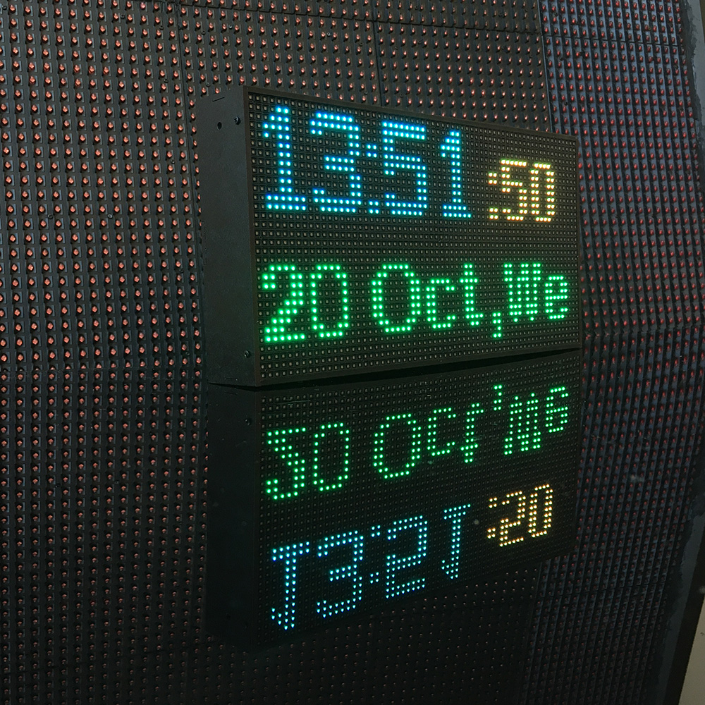
- always precise time (synchronization with NTP time servers)
- large clock (full screen) and small clock with additional information display (you can set a schedule for changing modes)
- display of current weather in your city and weather forecast (temperature, humidity, pressure, cloudiness, wind speed) on schedule
- display of the latest news on schedule
- reminder of events according to a specified schedule in the form of static text or creeping line
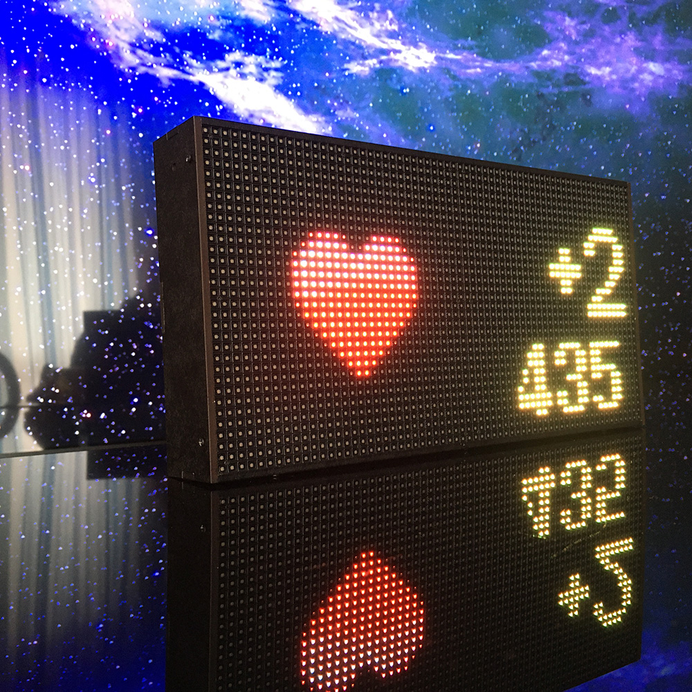
- three independent zones for displaying information
- high brightness even in direct sunlight
- setting the brightness for day and night mode
- information in three languages including Cyrillic
- control via web interface or mobile application
additionally for BUSINESS
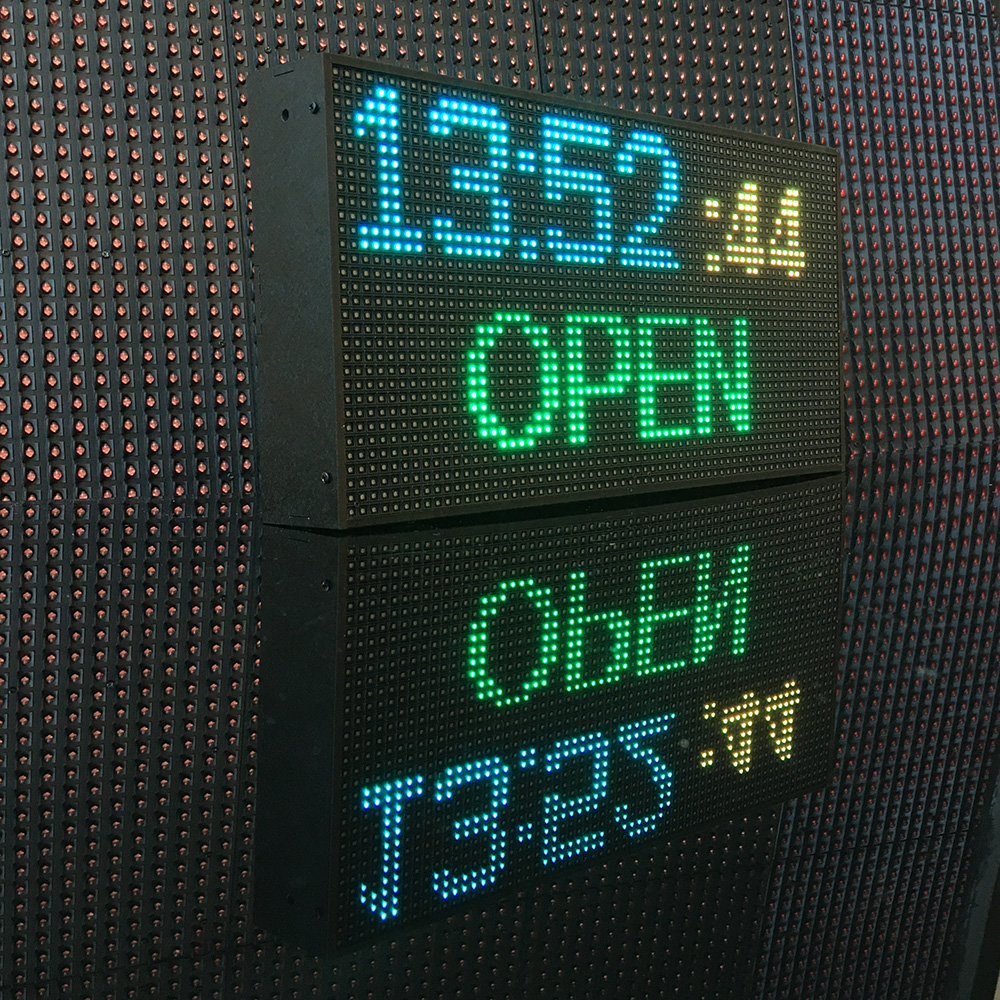
- inscriptions “OPEN” / “CLOSED” according to the work schedule of the store / office
- advertising inscriptions in Latin and Cyrillic on a schedule in the form of static text or creeping line
- excellent visibility of the displayed information even in bright ambient light
- setting the operating mode and brightness for day and night mode
additionally for BLOGGERS / VLOGGERS
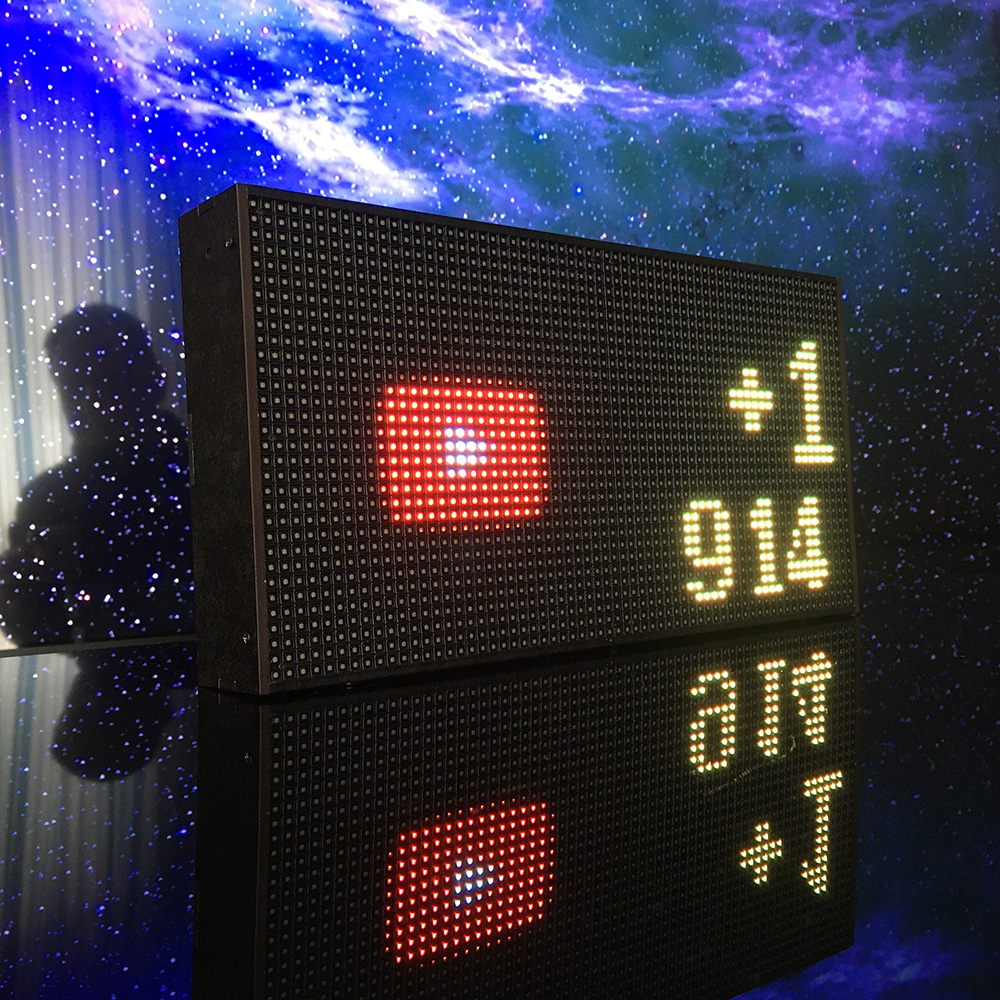
- display of the number of subscribers of the YouTube channel and the number of views of all videos
- displaying the number of Like a given video on YouTube, the number of views and comments to the video
- notification of new subscribers, new Likes and comments to a given video
For developers
- Hackable: Open source hardware and firmware, displays information read via UART
- firmware & filesystem update via Wi-Fi
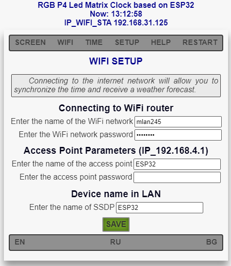
The information station is configured and controlled via the WEB interface or mobile application.
Thanks to Wi-Fi support, the device connects to the Internet and has the ability to synchronize time with time servers, receive weather data, weather icons, today’s date in various formats, news, information about likes and subscribers from Youtube, etc.
You can buy a fully assembled SmarTec information station in our store:
The code and instructions for the firmware can be downloaded GITHUB
Specifications:
| RGB LED matrix: | Size 256×128 mm Pixel Pitch 4mm (P4) Resolution 64×32 Brightness 1000 cd / m2 Scan rate 1/16 |
| Power supply: | 220V 50Hz |
| Power consumption: | 15 – 30 W |
| Protection: | IP50 |
| Control: | Wi-Fi (Web interface or mobile application) |
| Dimensions: |
262x134x38 mm |
What will you get in the package?
Each Information station SmarTec is a kit and comes with the following:
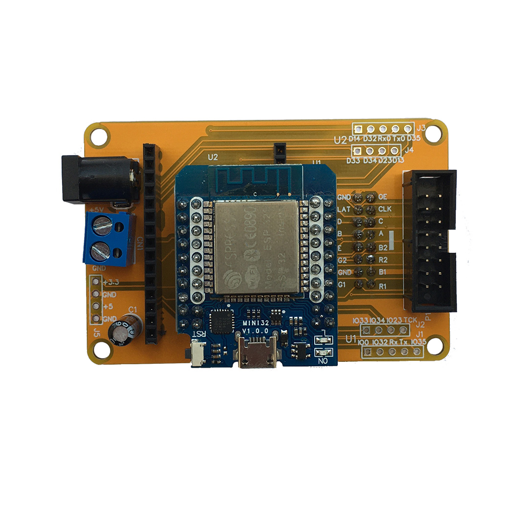
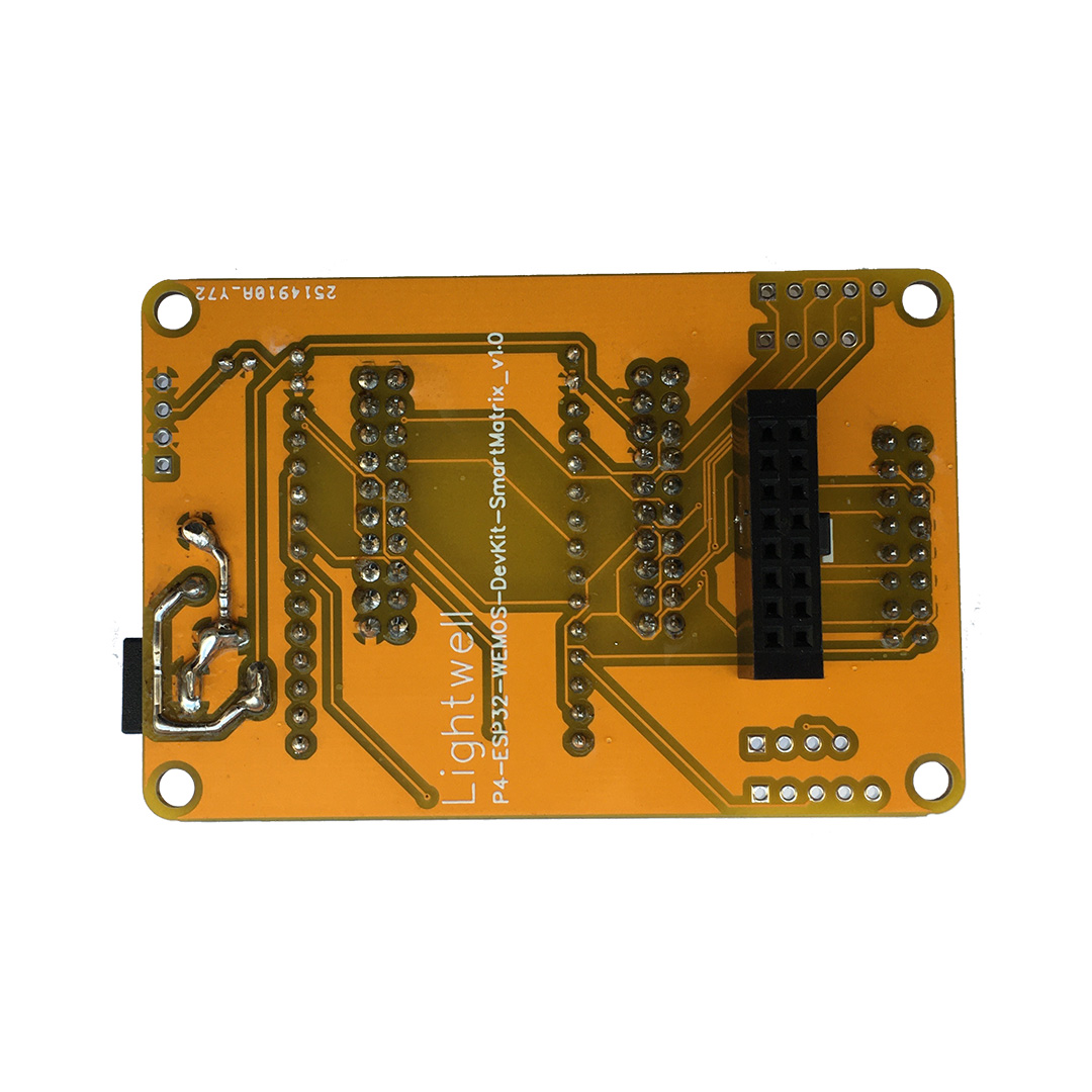
- RGB Matrix panel Shield PCB
- 10uF 25V Capacitor
- 1 pc 16 pin right angle male header (2×8)
- 1 pc 16 pin right angle female header (2×8)
- 2 pcs 15 pin right angle female header (1×15)
- 2 pcs 20 pin right angle female header (2×10)
- 2Pin Plug-in Screw Terminal Block Connector 5.08mm
- 2.1mm 6.3mm DC005-T20 AC/DC Power Connector
- RGB LED matrix panel P4 64×32 (256×128 mm) (option)
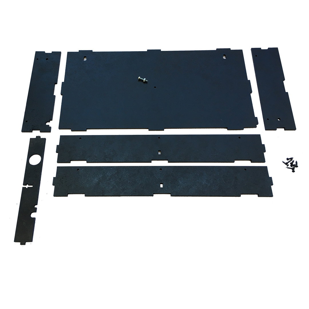
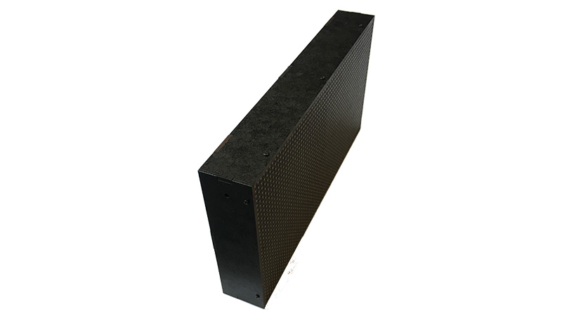
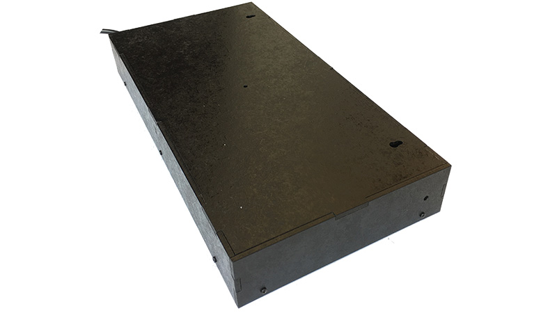
- Parts for case made of painted pressed plywood, screws and screw with nut for connection (option)
- External power supply 220V – 5V 5-8A (option)
- ESP32 30P WROOM-32 or Mini32 ESP32 Development Board (option)
Assembling the SmarTec KIT
1. Board assembly
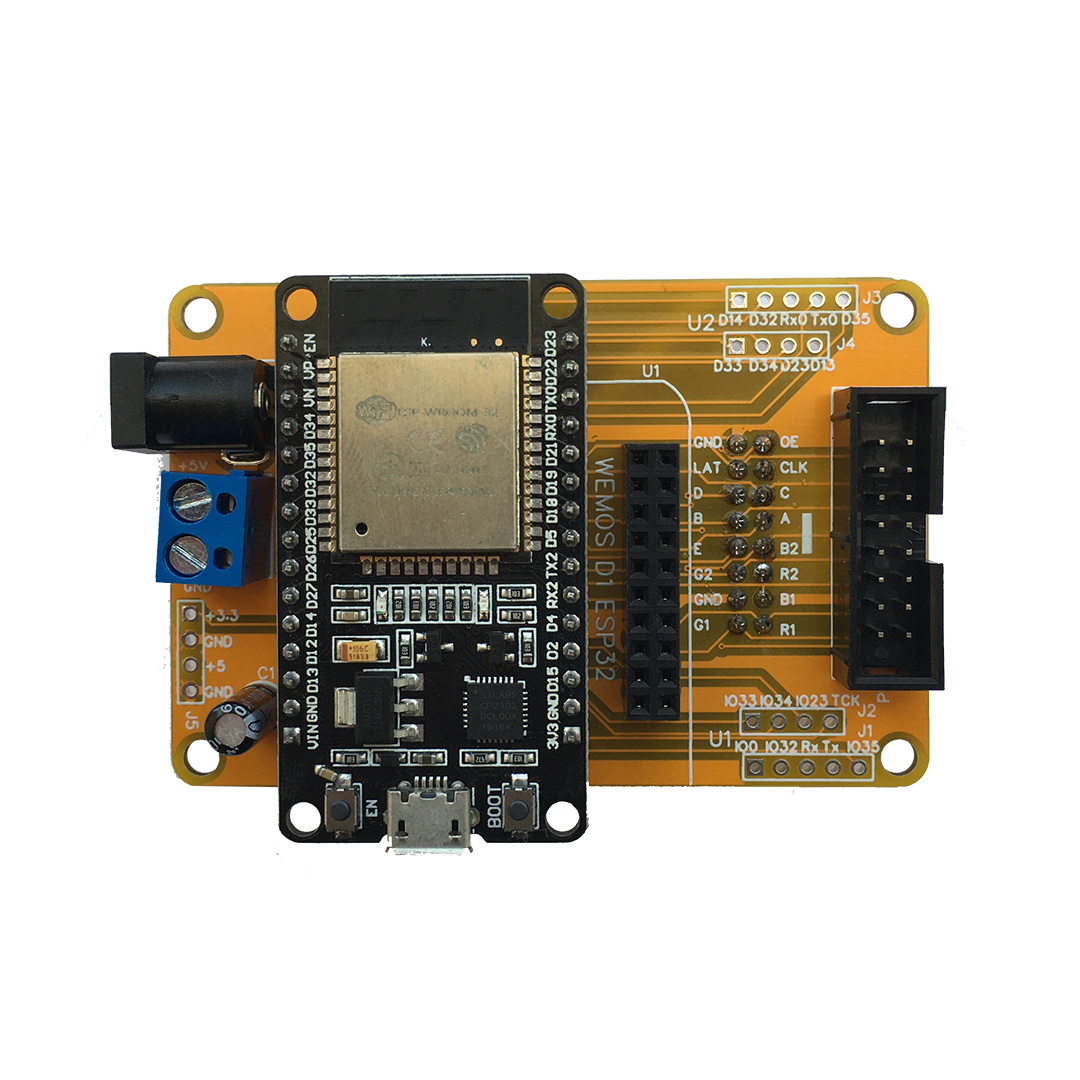
To assemble the boards, place the parts on the PCB as indicated by the markings on the PCB. All parts are places on the top of the PCB (as seen in the photos above) except for one 16 pin right angle female header that can be connected directly to the LED panel.
ESP32 Development Board (30P WROOM-32 or Mini32 ESP32) is placed on the board in accordance with the marking (USB and Antenna).
NOTE: Please pay attention to the polarity of the capacitor and the direction you are soldering the connectors!
2. Connecting the RGB Matrix panel Shield PCB to the RGB LED matrix panel
Insert the 16 pin right angle female header directly to the “Input” connector of LED panel.
OR
Insert the ribbon cable into the “Pout” connector on the shield, insert the other end into the “Input” connector of the panel.
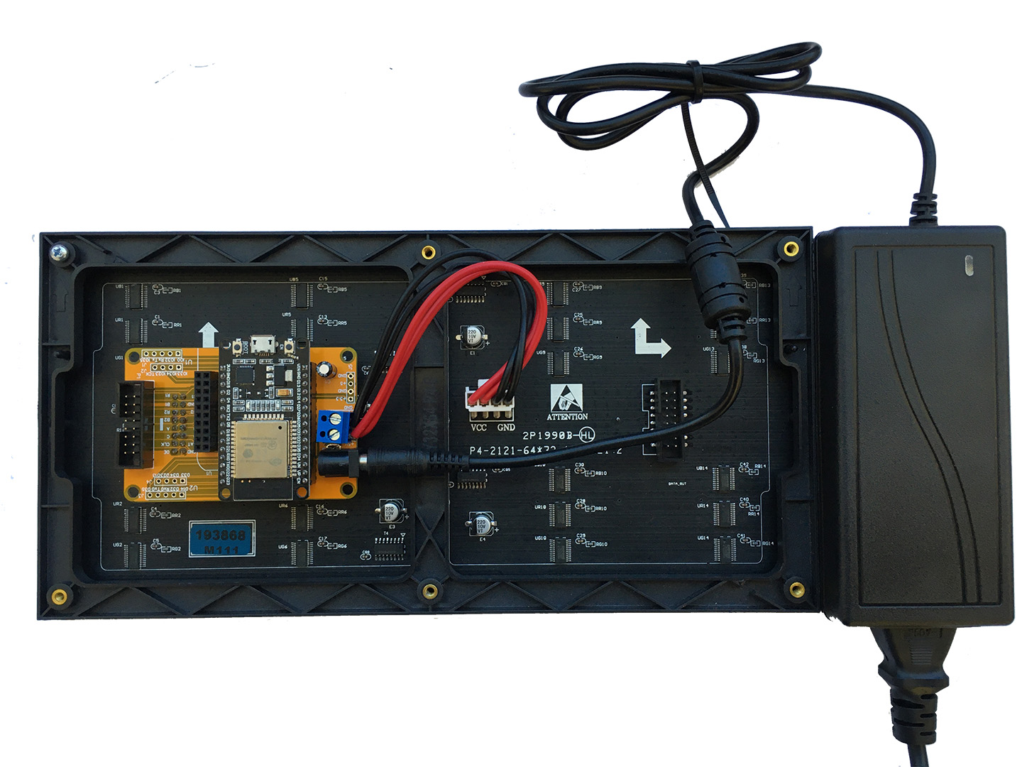
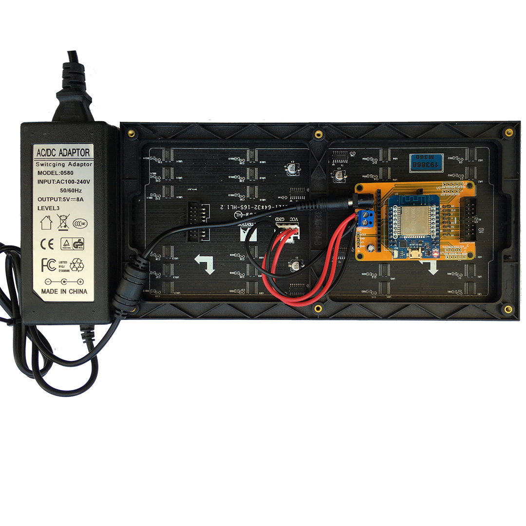
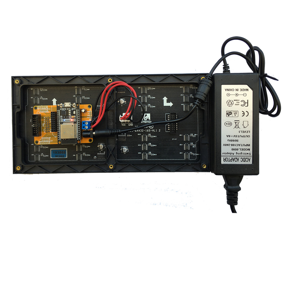
Plug the power wire that came with the display into the power pins of the panel. Attach the power wires to the 2Pin screw terminals on the shield (Pay close attention to the polarity!)
Schematic P4-ESP32-WEMOS-DevKit-SmartMatrix_v2.0
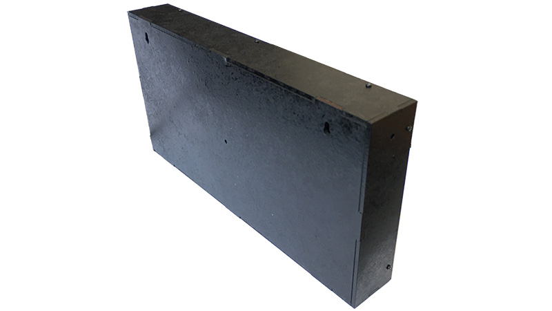
3. Assembly of the case
Assemble the body according to the attached drawing.
The parts of the case are attached to the LED panel with screws for which there are holes in them. You may need an awl or drill to make it easier to drive the screws into the panel.
The rear housing cover is secured with an M2 screw.
Powering the RGB Matrix panel Shield
These displays require a 5V power supply capable of doing roughly 4A of current.
Connect the external power supply to the PCB using 2.1mm 6.3mm DC005-T20 AC / DC Power Connector. Use 2Pin Plug-in Screw Terminal Block Connector 5.08mm to power the LED panel. The + 5V and GND tracks on the PCB have an increased cross-section, which allows you to safely connect the LED panel directly to the PCB.
| KIT 1 | KIT 2 | KIT 3 | |
| RGB Matrix panel Shield PCB | + | — | — |
| RGB Matrix panel power cable and signal cable | + | + | + |
| Parts for case made of painted pressed plywood, screws and screw and nut for connection | + | + | + |
| A set of elements (without installation on a PCB): – 10uF 25V Capacitor – 1 pc 16 pin right angle male header (2×8) – 1 pc 16 pin right angle female header (2×8) – 2 pcs 15 pin right angle female header (1×15) – 2 pcs 20 pin right angle female header (2×10) – 2Pin Plug-in Screw Terminal Block Connector 5.08mm – 2.1mm 6.3mm DC005-T20 AC/DC Power Connector |
+ | — | — |
| PCB mounted and soldered elements: – 10uF 25V Capacitor – 1 pc 16 pin right angle male header (2×8) – 1 pc 16 pin right angle female header (2×8) – 2 pcs 15 pin right angle female header (1×15) – 2 pcs 20 pin right angle female header (2×10) – 2Pin Plug-in Screw Terminal Block Connector 5.08mm – 2.1mm 6.3mm DC005-T20 AC/DC Power Connector |
— | + | + |
| RGB LED matrix panel P4 64×32 (256×128 mm) | — | — | + |
| External power supply 220V – 5V 5-8A | — | — | + |
| ESP32 30P WROOM-32 or Mini32 ESP32 Development Board with firmware & filesystem | — | — | + |

