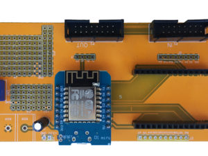
Opis
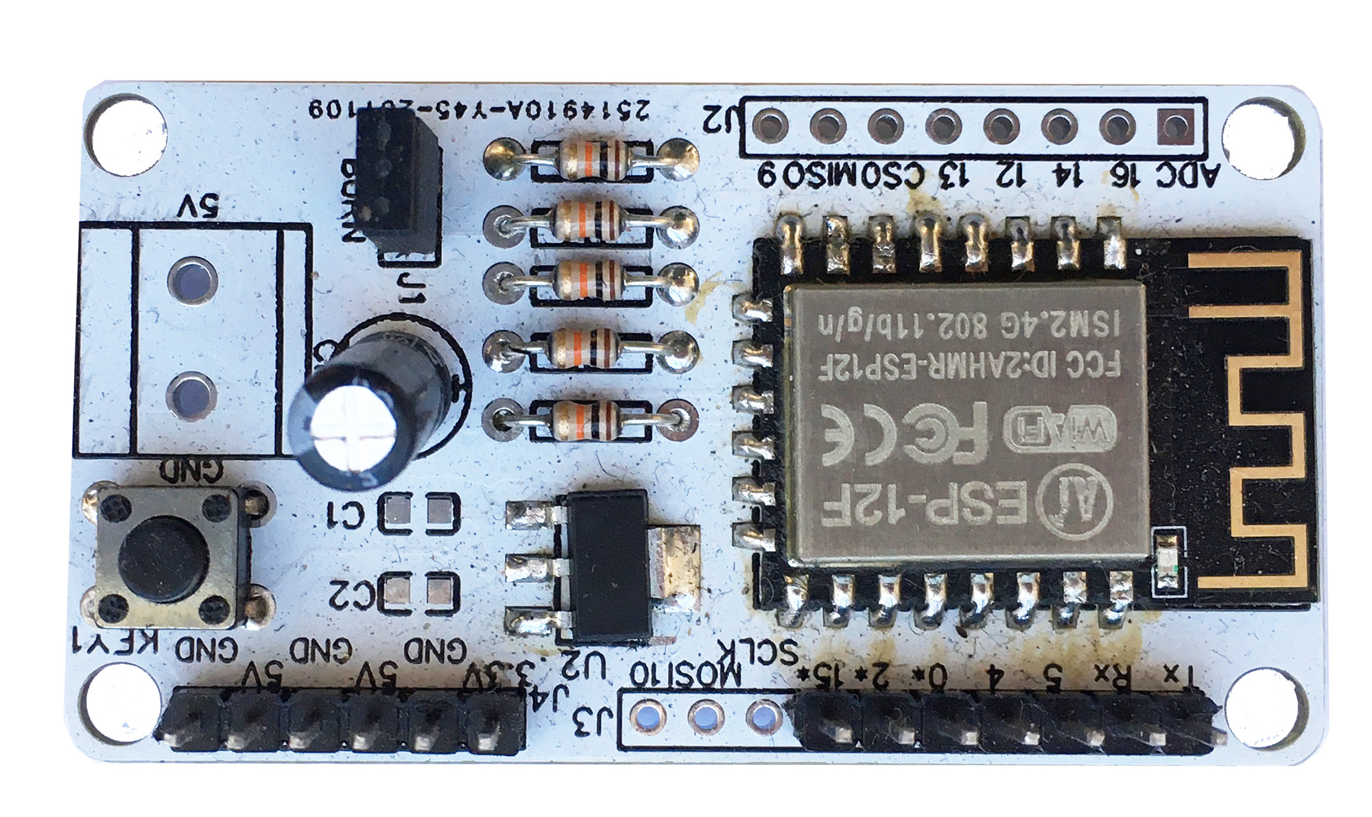
- You can connect most common USB to Uart programmers directly to the board, to flash or program your ESP-12 Module.
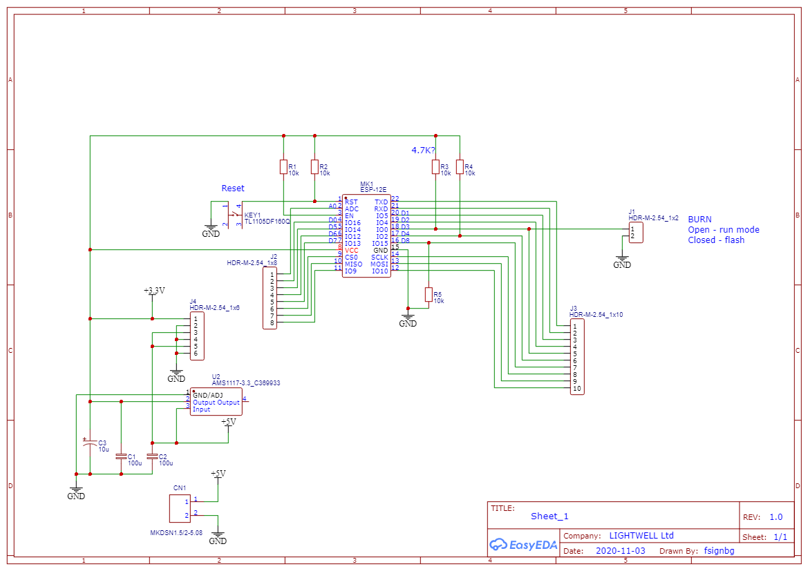
- There is a AMS1117-3.3V voltage regulator on board which accepts input voltages from 3.7 to 12V.
- The board contains the button which is connected to the reset pin.
- You can use a screw terminal to connect an external power source.
- TX and RX pins can be converted into GPIO, so that you can connect 4 external modules (i.e. control 4 relais or LEDs etc.).
- Breakout for up to 6 i2c modules (please note that the voltage regulator can provide maximum 250mA, so it will not work with power hungry i2c modules).
- For ESP-12 module there is a convenient female or mail pinheader connector.
What you get?
A single ESP-12 PCB without pin headers, just a board.
Available pins:
- UART RX/TX
- 9 GPIO pins: GPIO0, GPIO2, GPIO4, GPIO5, GPIO12, GPIO13, GPIO14, GPIO15, GPIO16
- 1 analog pin (ADC pin)
- RESET
- Powerdown (CH_PD pin)
- VCC (5V & 3.3V), GND
How to solder?
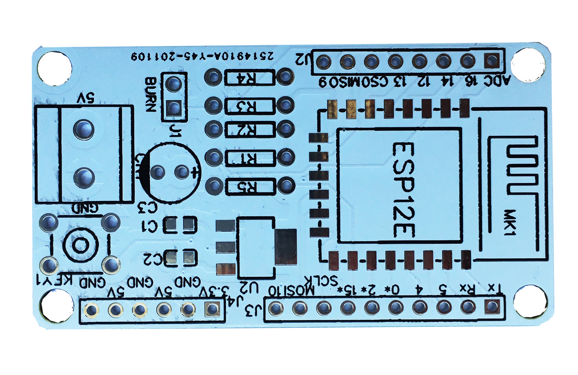
First solder the pin headers to the board and voltage regulator AMS1117-3.3V, then solder the ESP-12 module to the PCB, also don’t forget to connect GPIO-15 to the GND pin with a solder bridge.
ESP8266 documentation:
- ESP8266-Wiki
- NodeMcu (Lua interpreter for ESP8266)
- MQTT library for the ESP8266

