Opis
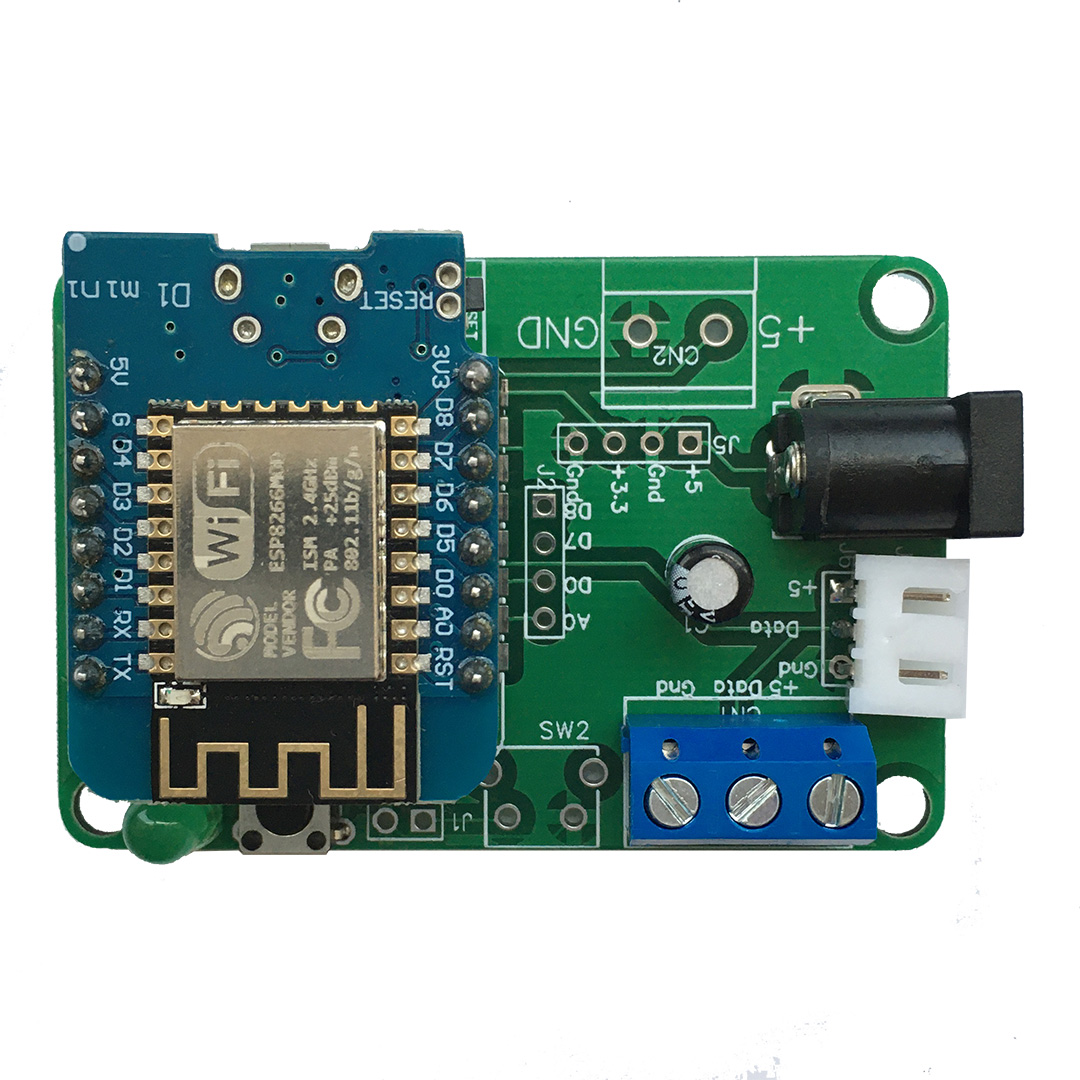
This is a shield for the Wemos D1 Mini ESP8266 board that makes it easy to control addressable LED strips or strands (RGB LEDs such as WS2811, WS2812, APA102 etc.).
The Wemos D1 Mini is an excellent mini Wi-Fi development board based on the ESP8266. We’ve used it extensively in development of addressable RGB LED art projects such as LED Pixel Clock https://github.com/Lightwell-bg/LEDPixelClock
You can use preset effects and color control programs that allow the controllable LEDs to be displayed.
Clock adjustment and manipulation is performed via button, WEB-interface or APP LWDevices or LWDevices2.
- https://play.google.com/store/apps/details?id=eu.ledlightwell.lwdevices
- https://play.google.com/store/apps/details?id=eu.ledlightwell.lwdevices2
Why did we make it?
Christmas and New Year are coming soon. Have fun with your own DIY Christmas Wi-Fi Pixel Controller!
Two connectors make it easy to connect the LED strip directly to the board. Power to the LED strip is supplied directly from the PCB for which the power lines are reinforced with additional soldering.
All you need to get colorful New Year’s effects is to connect the power supply (from 3A) and the LED strip to the PCB!
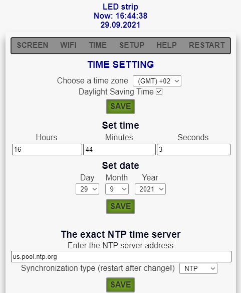
The original firmware (you can download it here github.com) provides for connecting to a home Wi-Fi network and receiving the exact time from an NTP server. This allows you to set the schedules for turning on and off the Christmas garland.
Below all it’s features:
- Control over 100 LEDs
- Compact PCB 60 x 40 mm
- Wiring through srew-plug terminal
- You can connect an external push button to operate with the LED
- Lighting effects on LED strip according to a given 29 program or randomly
- Day and night mode
- Ability to set work on a schedule because of synchronization with NTP time servers
- Control via button or WEB-interface from PC, tablet or smartphone
- High brightness
- Brightness adjustment
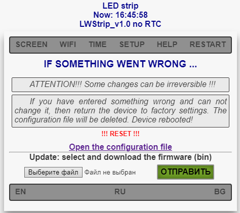
- Firmware update via Wi-Fi
- Information display on 3 languages: English, Russian, Bulgarian
- An option to install different alternative Open Source firmware
- Hackable: Open source hardware and firmware, Displays information read via UART
- Could be easily (re-)programmed
- Unused GPIOs are available on the PCB for future expansions or to add extra features
Specifications
- CPU: Tensilica L106 32-bit processor (ESP8266)
- Connectivity: WiFi 802.11 b/g/n, UART
- Upgradable: The software can be upgraded, either using an USB to UART module and over-the-air (OTA)
- Open source Software and Hardware code: https://github.com/Lightwell-bg/Wi-Fi-Pixel-Controller-for-addressable-LED-based-on-ESP8266
- Size: 60 x 40 x 1.6 mm
- 2 layer printed circuit board
Required Parts:
- ESP8266 (aka the ESP8266 D1 Mini): http://alii.pub/4d0k85
- 100uF 25V Capacitor
- 2 and 3 pin P=5.08mm Screw terminal
- 2.5mm 6.3mm DC005-T25 AC/DC Power Connectors
- 12VDC Round Button SPST 7.5×10.55mm Tactile Switches
- KEY-TH_4P-L6.0-W6.0-H4.3-LS7.5-P4.5 Tactile Switches
- Power supply 5V 8A – $11 from Aliexpress http://got.by/4d0ngf
Note: Using the links provided here help to support these types of projects. Thank you for the support.
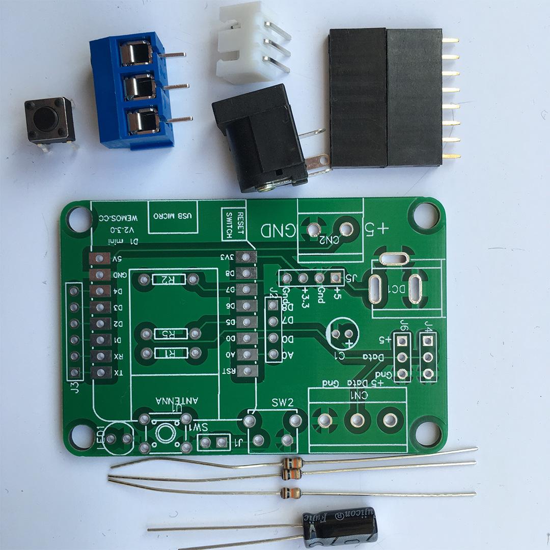
You can purchase a PCB with soldered elements and connectors for connecting the LED strip, or just a PCB and a set of elements for installation.
Assembly Options
The board can be assembled in a very low profile configuration (about 10mm thick) by soldering the Wemos directly to the PCB with only male headers and by mounting the large capacitor to the side.
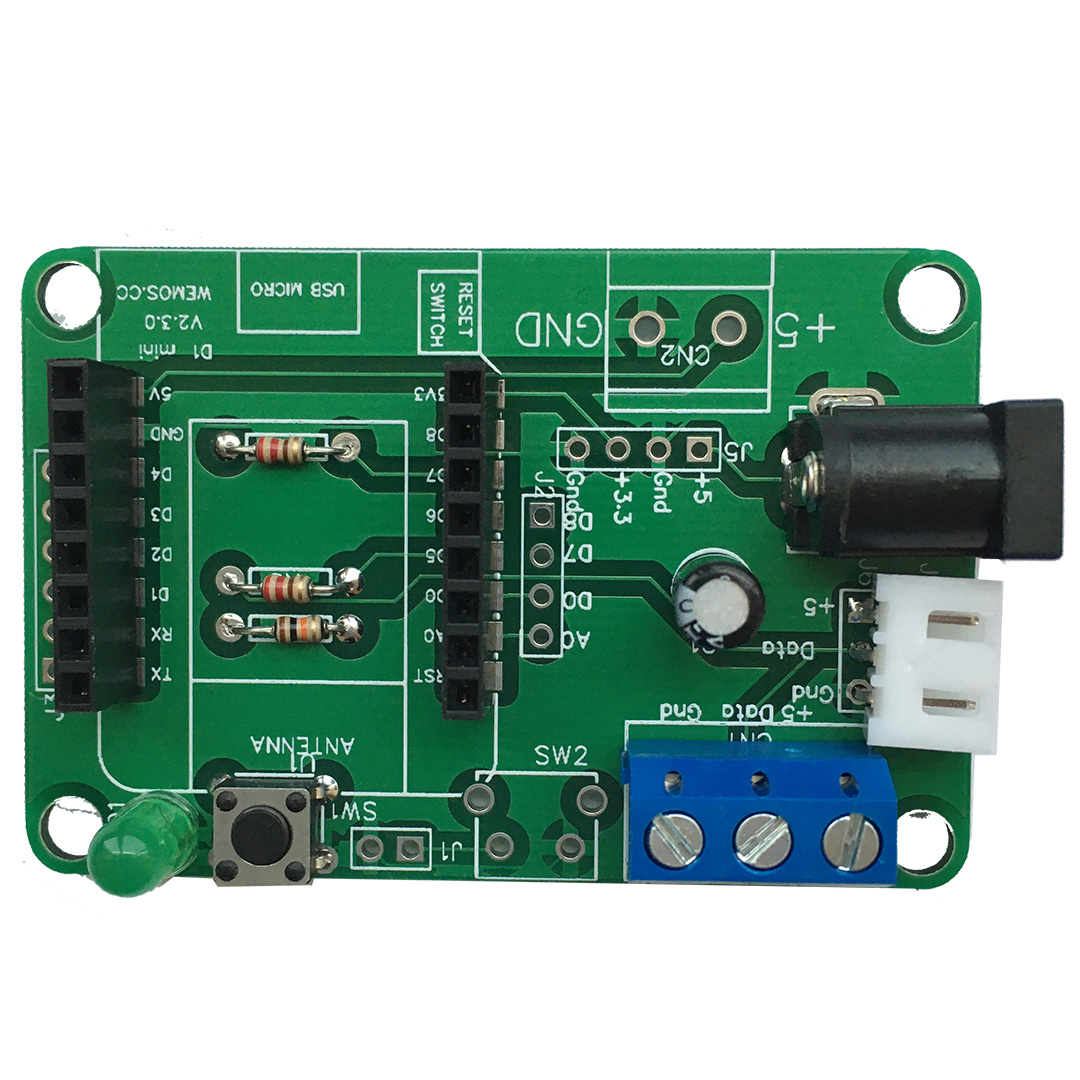
Alternatively, female headers can be used to allow easy removal of the Wemos microcontroller. This results in about 18mm of thickness.
To assemble the boards, place the parts on the PCB as indicated by the markings on the PCB. All parts are places on the top of the PCB (as seen in the photos above).
ESP8266 D1 Mini is placed on the board in accordance with the marking (USB).
NOTE: Please pay attention to the polarity of the capacitor and the direction you are soldering the connectors!
Button control
With the button you can control the following functions:
- One click – changing the effect of LED strip
- Double click – On/Off strip
- Long press – change brightness
Web Interface
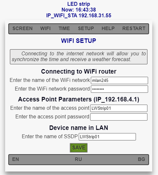
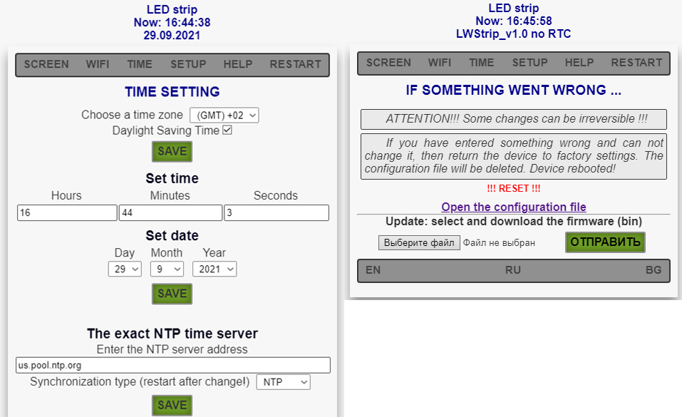
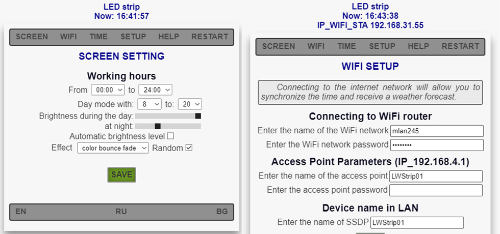
All device management is carried out using a web browser. On first power-up, Wi-Fi Pixel Controller will serve a hotspot called LWStrip01. For device adjustment and manipulation open a webpage with the 192.168.4.1 address. Within this hotspot you can manually override the time and date, show effect, brightness and update software.
For Wi-Fi network connection please input its SSID and password. After successful connection Wi-Fi Pixel Controller will begin to receive and transmit information over the Internet. NTP servers are used to get accurate time.
What will you get in the package?
Each Wi-Fi Pixel Controller is a kit and comes with the following:
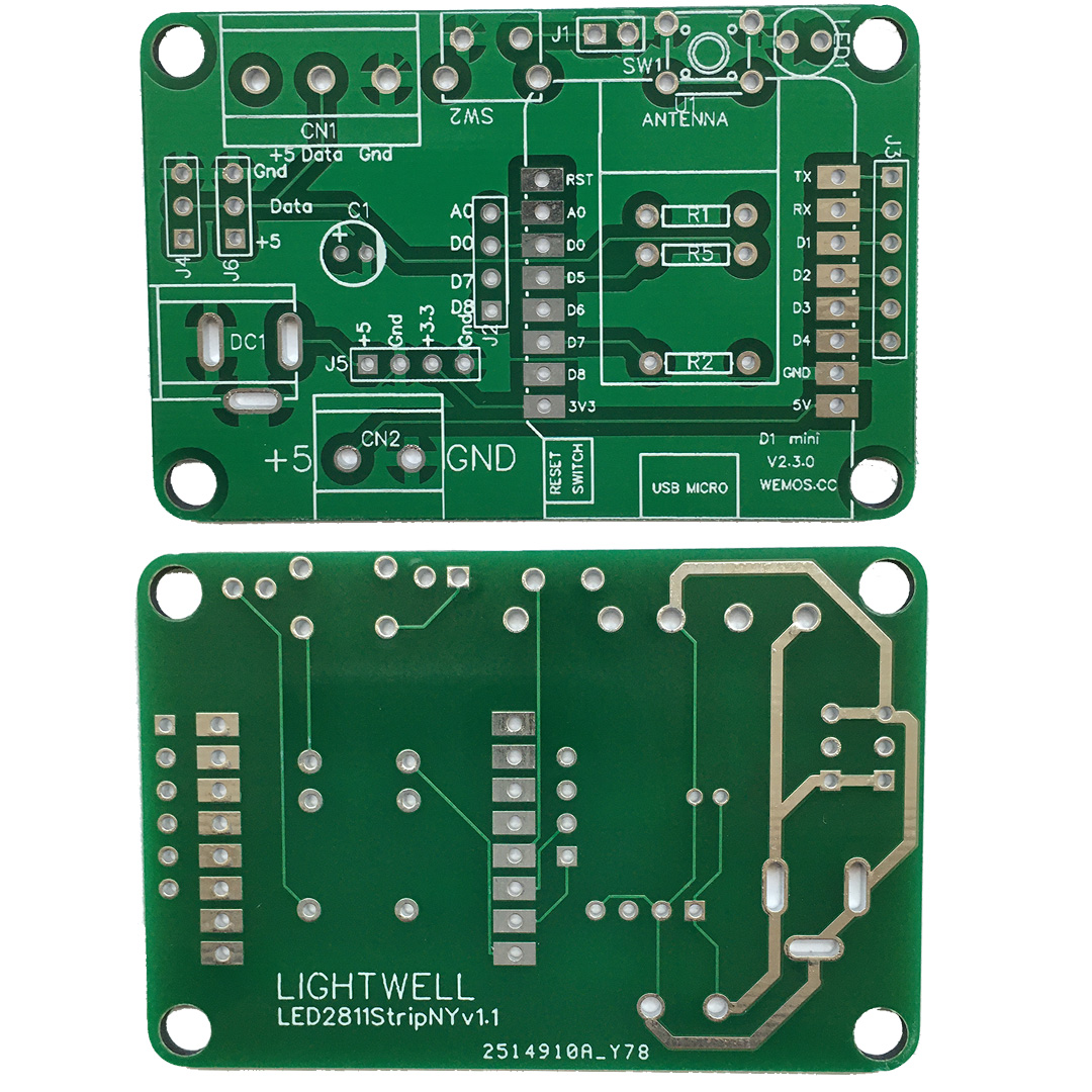
- Wi-Fi Pixel Controller Shield PCB
- 100uF 25V Capacitor
- 3Pin Plug-in Screw Terminal Block Connector 5.08mm
- 5mm 6.3mm DC005-T25 AC/DC Power Connectors
- KEY-TH_4P-L6.0-W6.0-H4.3-LS7.5-P4.5 Tactile Switches
What is NOT included?
The following components are not provided, but are required to use this board.
- ESP8266 (aka the ESP8266 D1 Mini): http://alii.pub/4d0k85
- Power supply 5V 8A – $11 from Aliexpress http://got.by/4d0ngf
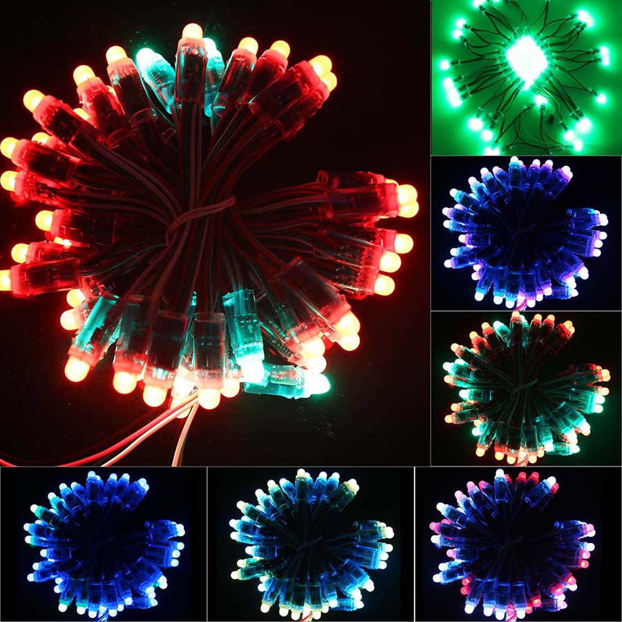
- 50pcs DC 5V input WS2811 Full Color LED Pixel Light Module 12mm IP68 waterproof RGB http://alii.pub/64c7uq
What Comes In A Kit?
| KIT 1 | PCB with soldered all elements and connectors for connecting the LED strip |
| KIT 2 | PCB and a set of elements for installation (see “What will you get in the package”) |
| KIT 3 | Wi-Fi Pixel Controller Shield PCB only |

